Search icon CANCEL
Subscription
0
Cart icon
Your Cart (0 item)
Close icon
You have no products in your basket yet
Arrow left icon
Explore Products
Best Sellers
New Releases
Books
Videos
Audiobooks
Learning Hub
Free Learning
Arrow right icon
Arrow up icon
GO TO TOP
Internet of Things Programming with JavaScript

You're reading from   Internet of Things Programming with JavaScript Get the best out of Arduino and Raspberry Pi Zero to develop Internet of Things projects using JavaScript

Arrow left icon
Product type Paperback
Published in Feb 2017
Publisher Packt
ISBN-13 9781785888564
Length 298 pages
Edition 1st Edition
Languages
Tools
Arrow right icon
Author (1):
Arrow left icon
Ruben Oliva Ramos Ruben Oliva Ramos
Author Profile Icon Ruben Oliva Ramos
Ruben Oliva Ramos
Arrow right icon
View More author details
Toc

Table of Contents (10) Chapters Close

Preface 1. Getting Started with Raspberry Pi Zero FREE CHAPTER 2. Connecting Things to the Raspberry Pi Zero 3. Connecting Sensors - Measure the Real Things 4. Control-Connected Devices 5. Adding a Webcam to Monitor Your Security System 6. Building a Web Monitor and Controlling Devices from a Dashboard 7. Building a Spy Police with the Internet of Things Dashboard 8. Monitoring and Controlling Your Devices from a Smart Phone 9. Putting It All Together

Connectting digital input - sensor DS18B20


The Raspberry Pi has digital pins, so in this section, we will look at how to connect a digital sensor to the board. We will use the digital sensor DS18B20, which has a digital output and can be perfectly connected to a digital input in our Raspberry Pi sensor. The main idea is to take temperature readings from the sensor and display them on the screen.

Hardware requirements

We will require the following hardware to take the temperature reading:

  • Temperature sensor DS18B20 (waterproof)

  • One resistor of 4.7 kilo-ohms

  • Some jumper wires

  • A breadboard

We will use a waterproof sensor DS18B20 and a 4.7 kilo-ohm resistor:
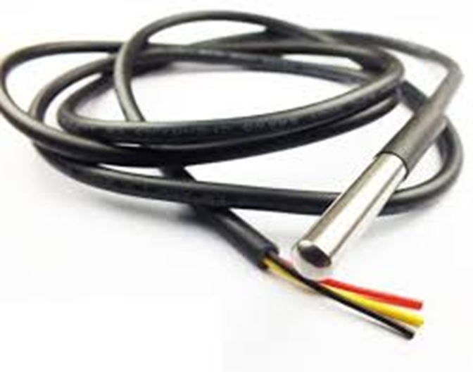
This is the waterproof sensor that we are using in this project.

Hardware connections

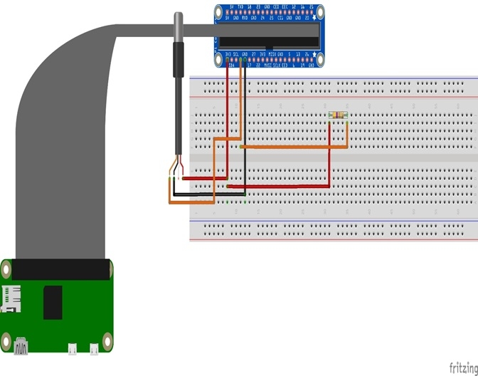
The following diagram shows the circuit on the breadboard, with the sensor and the resistor:
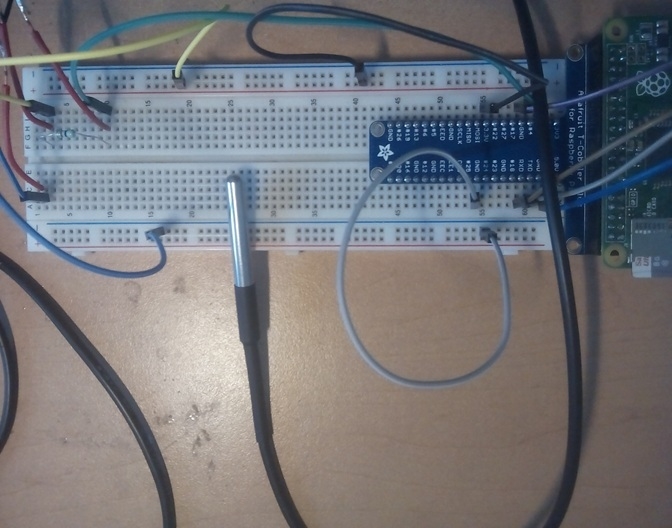
In the following image, we can see the circuit with the sensor:
lock icon The rest of the chapter is locked
Register for a free Packt account to unlock a world of extra content!
A free Packt account unlocks extra newsletters, articles, discounted offers, and much more. Start advancing your knowledge today.
Unlock this book and the full library FREE for 7 days
Get unlimited access to 7000+ expert-authored eBooks and videos courses covering every tech area you can think of
Renews at $19.99/month. Cancel anytime
Banner background image