Chapter 9. Grove Sensors and the Raspberry Pi
In the previous chapter, we discussed object detection and tracking and also learned to detect motion in scenes. Along the way, we also learned various concepts of image processing that may also be used for different applications.
In this chapter, we will be moving forward from the software-based approach of the previous chapter and explore the hardware capabilities of the Raspberry Pi. We will also learn about an add-on called the GrovePi Shield, which will extend the GPIO capabilities of the Pi platform and make it even easier to connect new sensors to it. In this chapter, we will learn about the following:
- Introducing the GrovePi Shield and sensors
- Setting up the Shield with the Raspberry Pi
- Building a weather station
- Building an intruder detection system
Introducing the GrovePi
The GrovePi Shield is an open source platform to connect a range of sensors called the Grove sensors to the Raspberry Pi. We can create our own Internet of Things applications without any need for soldering using the GrovePi! Grove is an easy-to-use collection of more than a hundred Plug and Play modules that we can use to sense and interact with the physical world. The array of sensors include relays, temperature sensors, OLED displays, ultrasonic ranger, joystick, accelerometer, humidity sensor, GPS, and so on. They are divided on the basis of the following six categories: Environment Monitoring, Motion Sensing, User Interface, Physical Monitoring, Logic Gate, and Power.
You can interact and monitor the world using the sensors and then store the data on your Raspberry Pi bridging the gap to the real world!

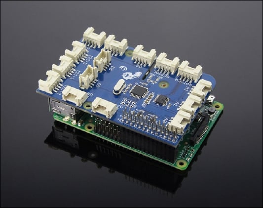
As you can see from the preceding image, the GrovePi slips over the Raspberry Pi and has a variety of sockets to hold the different sensors that you might want to add to your Raspberry Pi. It works with the Raspberry Pi models A, A+, B, B+, 2, and uses an open source library made available by its creators to allow users to program in Python, C, C++, Go, and NodeJS.
For this chapter, we will need the following components:
- Humidity and temperature sensor (http://www.seeedstudio.com/depot/Grove-TempHumi-Sensor-p-745.html?cPath=25_125)
- LED (http://www.seeedstudio.com/depot/Grove-Red-LED-p-1142.html?cPath=81_35)
- Ultrasonic ranger (http://www.seeedstudio.com/depot/Grove-Ultrasonic-Ranger-p-960.html?cPath=25_31)
- OLED display (http://www.seeedstudio.com/depot/Grove-OLED-Display-096-p-824.html?cPath=34_36)
- Buzzer (http://www.seeedstudio.com/depot/Grove-Buzzer-p-768.html?cPath=38)
- GrovePi+ (http://www.seeedstudio.com/depot/GrovePi-p-2241.html)
All of the preceding are available on the SeeedStudio website.
Note
You can find out more about the GrovePi and the sensors on their creator's website:
Setting up the GrovePi
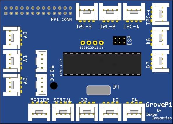
Let us have a look at an image of the GrovePi:

As you can see from the preceding image, GrovePi has a socket that allows it to fit directly over the Raspberry Pi. Once we do that, we can begin to set up the software on the Raspberry Pi to use the shield. The steps are given next.
- Turn on the Raspberry Pi without the GrovePi attached and open a terminal window either by using a monitor or through ssh:

- It is recommended that we install GrovePi on the desktop so we first cd into the desktop directory with the following command:
$ cd /home/pi/Desktop - Now clone the repository from GitHub into the desktop with the following command:
$ sudo git clone https://github.com/DexterInd/GrovePi
- We are now ready to execute the install script for the GrovePi. But we must first make the script executable and then run it:
$ cd /home/pi/Desktop/GrovePi/Script
$ sudo chmod +x install.sh
$ sudo ./install.sh

- The terminal will ask you to press ENTER and subsequently Y to continue, so please do press Enter to install all the required packages.

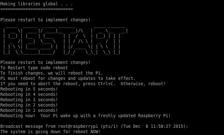
The setup will now be completed and your Raspberry Pi will be restarted automatically. With the Raspberry Pi powered off, attach the GrovePi and then turn it on.

Now we will check if the Raspberry Pi detected the GrovePi upon reboot. Run:
$ sudo i2cdetect -y 1
The command i2cdetect detects any peripherals that are connected to the I2C Pins of the Raspberry Pi, which are GPIO02 and GPIO03 in the case of Pi B+ and Pi 2. These are the pins that the GrovePi Shield uses to establish a connection to the Raspberry Pi.
In case you have a Raspberry Pi model that was produced before October 2012, you can run the following:
$ sudo i2cdetect -y 0

If you see a '04' in the output matrix, that means the GrovePi is detected by the Raspberry Pi I2C port. We can now test to see if it works properly. To test, connect an LED module to the D4 port and run the LED Blink Python example that comes bundled with the Github repository we cloned in an earlier step. To do that, run the following command:
$ cd /home/pi/Desktop/GrovePi/Software/Python
$ sudo python grove_led_blink.py
If everything was installed correctly in the previous steps, the LED on port D4 should now start blinking.

Congratulations, we have successfully set up the GrovePi to work with the Raspberry Pi and we will now move on to some complex and interesting examples to explore the functionality of the GrovePi.
Displaying the weather
For our first project, we will be using the humidity and temperature sensor of the gross array and use its measurements to be displayed on an OLED display. You will need the two modules and some connection cables to set up the hardware for this project.

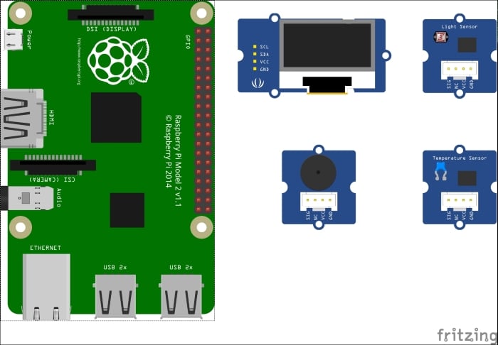
Connect the only display module to any of the three i2c ports on the GrovePi, and connect the humidity and temperature sensor to port D7. Now we will have a look at the following code and then learn what each statement does:
from grovepi import *
from grove_oled import *
dht_sensor_port = 7
oled_init()
oled_clearDisplay()
oled_setNormalDisplay()
oled_setVerticalMode()
time.sleep(.1)
while True:
       try:
        [ temp,hum ] = dht(dht_sensor_port,1)
        print "temp =", temp, "C\thumidity =", hum,"%"
        t = str(temp)
        h = str(hum)
        oled_setTextXY(0,1)
        oled_putString("WEATHER")
        oled_setTextXY(2,0)
        oled_putString("Temp:")
        oled_putString(t+'C')
        oled_setTextXY(3,0)
        oled_putString("Hum :")
        oled_putString(h+"%")
        except (IOError,TypeError) as e:
        print "Error"
Save the preceding code as prog1.py and run it. You should see the temperature and humidity values being reported on the terminal, as well as on the OLED screen:

The first two statements are responsible for importing the dependencies required for the GrovePi Shield and OLED module to work. The asterisk tells Python to import all the classes and functions from the given modules. The second statement creates a variable where the port number for the DHT module is saved. The next statements set up the OLED module for writing data to it. The functions initialize the module, clear the display, and set the vertical mode so that if we write anything subsequently it appears natural. It is recommended that these four statements be executed at the start of any Python program that uses the OLED module.
Next, we add an infinite while loop so that the program keeps on running until the user terminates it. Inside the while loop, we run the code that is responsible for getting the data from the sensor and displaying it on the OLED module. One of the common mistakes when getting data from any source is that the data might not be available. So we always check the validity and availability of data before executing any code to manipulate or use that data. This is why we must add a try catch statement so that if the data is not available, the program does not crash but gives us an error statement.
Inside the try block, our first statement is to get the data from the DHT module using the dht() function. This function takes two arguments: the sensor port number and the type of board connected. We'll enter 1 if the board is DHT Pro and 0 if the board is DHT. It also gives us the output in the form of a list containing two elements: the temperature and humidity level.
In the next statement, we print the humidity level and temperature to the terminal so that the user can look at it. The values that we get from the dht() command are integers, but to display them on the OLED screen we need to convert them to strings. This is what the str() method does. It takes an input like integer, float, list, and so on and gives a string output.
The subsequent commands that begin with oled_ are all to manipulate the display of the data on the OLED screen. With the oled_setTextXY() method, we can set the cursor to display the data. It takes the X and Y coordinates as arguments and sets the cursor there. Next, with the oled_putString() method, we actually push the string data to be displayed on the cursor we just set. We do this three times: first to set the title as 'WEATHER', second to set the temperature and its units, and finally to set the humidity and its percentage. Since this method only takes the string as input, it was necessary to convert the integer values of temperature and humidity to the string before using it here.
Finally, we read the last statement that does nothing but handle any error that might be encountered in the try block. If it does encounter an error of any sort, it prints Error instead of crashing.
We will now move on to our next project, which uses an ultrasonic sensor and a Pi Camera (or a normal webcam if you so choose). Any idea about what we're going to make?
Intruder detection system
Do you have any data that would cause damage if it fell into the wrong hands? Or do you wish to know who enters a specific place when you're not present? Well, you can now easily answer these questions by building your own intruder detection system!
As mentioned before, this project uses an ultrasonic range sensor for the GrovePi and a PiCam to take pictures if any movement is detected by the ultrasonic ranger. Connect the ultrasonic ranger to port D4 of the Grove Pi, the buzzer to D5, the status LED to D3, and the Pi Camera to the port provided on the Raspberry Pi as learned in Chapter 4, Working with Webcam and Pi Camera. Following the theme of the book, we will first look at the whole code, and then learn what each statement does, line by line:
import picamera
import grovepi
from time import sleep

camera = picamera.PiCamera()
counter = 0
led = 3
buzzer = 5
ultrasonic = 4

while True:
    try:
        if grovepi.ultrasonicRead(ultrasonic) < 100:
        print 'Intruder Detected'
            grovepi.analogWrite(buzzer, 100)
            grovepi.digitalWrite(led, 1)
            sleep(.5)
            grovepi.analogWrite(buzzer, 0)
        grovepi.digitalWrite(led, 0)
            camera.capture('image' + counter + '.jpg')
            print 'Image Captured'
        sleep(2)
    except IOError:
        print "Error"
Save the preceding code as prog2.py and run it. Now, try to come in front of the ultrasonic sensor and you will see the output on the terminal, and have your picture taken as an intruder!
The code itself is very simple to understand, as it is just an amalgamation of parts from Chapter 4, Working with Webcam and Pi Camera, which we have already learned, and parts from the previous example. We start by importing the dependencies for the Pi Camera and GrovePi sensors.
As a setting-up step, we set the camera variable to be an object for our Pi Camera and it can be used to take pictures. We set a counter for the number of pictures and set the LED and buzzer to be used on ports D3 and D5 respectively. We also import the sleep method from the 'time' module to add delays. Like before, we include a 'try, except' block in the infinite while loop, so that when errors are encountered, it does not crash.
Basic algorithm for the intruder detection can be described as: Whenever anything comes in front of the ultrasonic ranger whose range is less than 100 cms, it means that there is an intruder. If the preceding condition is true, then sound the buzzer, light the LED, and take a picture. The ultrasonicRead() method from the GrovePi module reads the output from the ultrasonic ranger that is connected to port D7 of the GrovePi. If the distance is less than 100 cms, then we proceed to execute the intruder detection alarm procedure. First, we output Intruder detected to the terminal, then we turn on the buzzer by the analogWrite() method and the LED with the digitalWrite() method. The analogue write method takes the port number of the peripheral and a value from 0 to 255. The higher the value, the higher the intensity of the signal transmitted to the peripheral. The digitalWrite() method also takes the port number as an input and a binary number, to set the port high or low. We wait for half a second and then turn both the buzzer and LED off. Finally, we capture a photo with the camera pointed toward the direction of the ultrasonic ranger. Congratulations! We now have a photo of the intruder. Now, if we do not add some delay after taking a photo, the code will repeat itself and since the intruder is likely to still be there, the Raspberry Pi may take an unnecessarily large amount of photos. This is likely to burden the CPU and take resources away from other threads that might be running. So we add a two-second delay.
We can also experiment by varying the delay values to see what works best. I leave the reader with an interesting exercise of adding more peripherals to expand the functionality of the system, such as adding a keypad or a switch to turn off the system when it is not required.
Summary
In this chapter, we learned how to connect and interface the GrovePi Shield with the Raspberry Pi, and how to connect the various sensors to it, and use their data to display on external peripherals. We also looked at and understood two examples that can be used easily in real life for useful tasks.
In the next chapter, we will learn about the Internet of Things and how to connect sensors to get the data online and use it effectively. For example, we can extend the intruder detection example and make it such that it e-mails us the photo of the intruder it just took. In this way, we can receive real-time updates from our chosen monitored location. The Internet of Things is a very useful concept and due to the inexpensiveness of the components it takes to get a working system, it is becoming very popular across the globe to make 'dumb' devices 'intelligent'.


