Search icon CANCEL
Subscription
0
Cart icon
Your Cart (0 item)
Close icon
You have no products in your basket yet
Arrow left icon
Explore Products
Best Sellers
New Releases
Books
Videos
Audiobooks
Learning Hub
Free Learning
Arrow right icon
Arrow up icon
GO TO TOP
The FPGA Programming Handbook

You're reading from   The FPGA Programming Handbook An essential guide to FPGA design for transforming ideas into hardware using SystemVerilog and VHDL

Arrow left icon
Product type Paperback
Published in Apr 2024
Publisher Packt
ISBN-13 9781805125594
Length 550 pages
Edition 2nd Edition
Languages
Tools
Arrow right icon
Authors (2):
Arrow left icon
Guy Eschemann Guy Eschemann
Author Profile Icon Guy Eschemann
Guy Eschemann
Frank Bruno Frank Bruno
Author Profile Icon Frank Bruno
Frank Bruno
Arrow right icon
View More author details
Toc

Table of Contents (17) Chapters Close

Preface 1. Introduction to FPGA Architectures 2. FPGA Programming Languages and Tools FREE CHAPTER 3. Combinational Logic 4. Counting Button Presses 5. Let’s Build a Calculator 6. FPGA Resources and How to Use Them 7. Math, Parallelism, and Pipelined Design 8. Introduction to AXI 9. Lots of Data? MIG and DDR2 10. A Better Way to Display – VGA 11. Bringing It All Together 12. Using the PMOD Connectors – SPI and UART 13. Embedded Microcontrollers Using the Xilinx MicroBlaze 14. Advanced Topics 15. Other Books You May Enjoy
16. Index

Project 7 – Using the temperature sensor

The Nexys A7 board has an Analog Device ADT7420 temperature sensor. This chip uses an industry-standard I2C interface to communicate. This two-wire interface is used primarily for slower-speed devices. It has the advantage of allowing multiple chips to be connected through the same interface and be addressed individually. In our case, we will be using it to simply read the current temperature from the device and display the value on the seven-segment display.

Our first step will be to design an I2C interface. In Chapter 8, Introduction to AXI, we’ll be looking at designing a general-purpose I2C interface, but for now, we’ll use the fact that the ADT7420 comes up in a mode where we can get temperature data by reading two I2C memory locations. First, let’s look at the timing diagram for the I2C bus and the read cycle we’ll be using:
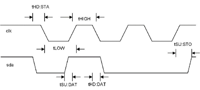
Figure 6.13: I2C timing

We can see from the timing diagram...

lock icon The rest of the chapter is locked
Register for a free Packt account to unlock a world of extra content!
A free Packt account unlocks extra newsletters, articles, discounted offers, and much more. Start advancing your knowledge today.
Unlock this book and the full library FREE for 7 days
Get unlimited access to 7000+ expert-authored eBooks and videos courses covering every tech area you can think of
Renews at $19.99/month. Cancel anytime
Banner background image