Introducing Vivado
Once you have selected a board, the best way to get to know it is to work through an example design.
Vivado is the Xilinx tool we will be using to implement, test, download, and debug our designs. It can be run as a command-line tool in non-project mode, or in project mode using the GUI. For our purposes, we will be using project mode via the GUI; however, we will go through non-project mode as an introduction in the Appendix.
Vivado installation
Xilinx makes Vivado freely available in the form of a webpack for smaller devices. The webpack contains all the features of the full version with a limitation based on device support. It is available for either Windows or Linux. This book will show screenshots for the Linux version; however, everything is tested on both, so you will be fine with using either.
Important note
The Xilinx webpack forces tool feedback information to Xilinx. The paid version allows this to be disabled.
Perform the following steps to effect installation:
- Create an account at https://www.xilinx.com/.
- Visit https://www.xilinx.com/support/download.html.
- Download the Xilinx Unified Installer. For this book, we'll be using version
2020.1. - On Windows, run the
.exefile.On Linux, use the following commands:
chmod +x Xilinx_Unified_2020.1_0602_1208_Lin64.bin; ./Xilinx_Unified_2020.1_0602_1208_Lin64.bin
- Enter your account information for the installation.
- When prompted, you can install either Vitis or Vivado. We will not be using Vitis, but it includes Vivado, so if you are adventurous and want to try Vitis out, feel free to install this as well.
- When prompted for the devices, you only need the 7 Series.
- Pick an installation location or use the default option.
Once you've completed these steps, get a cup of coffee… take a nap… write a book. It is going to take a while.
Directory structure
With Vivado installed, we can now walk through a very simple project to introduce you to Vivado and to make sure everything is set up correctly. The directory structure I like to use looks like the following:
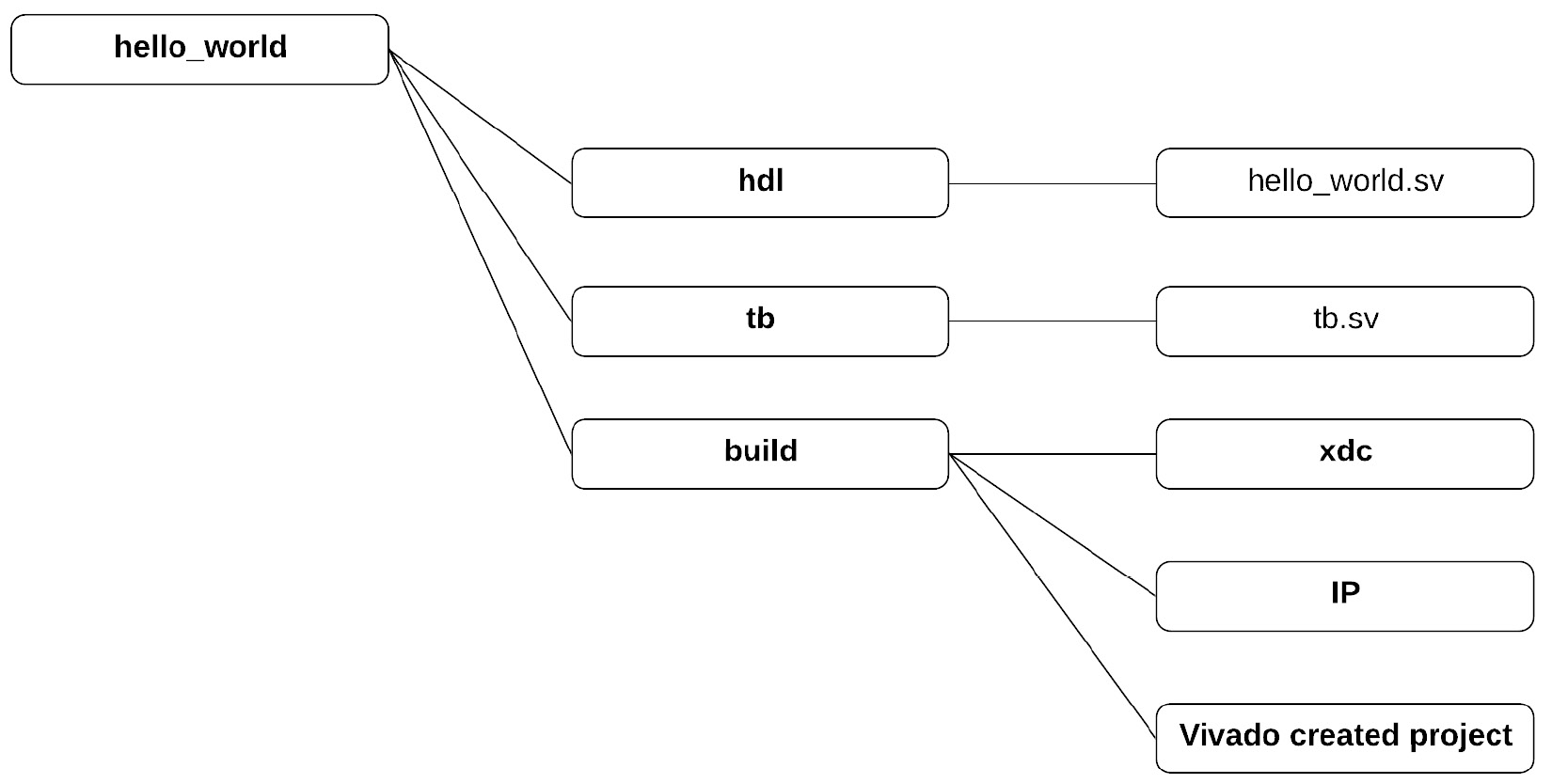
Figure 1.13 – Directory structure
Items in bold are directories. For our first example design, we do not have a lot of code. We will end up creating only three files: the HDL source code, the testbench, and a constraints file.
Inside the hdl directory, we'll create a simple design, logic_ex.sv, to run through Vivado:
Logic_ex.sv
`timescale 1ns/10ps
module logic_ex
  (
   input  wire  [1:0]    SW,
   output logic [3:0]    LED
   );
  assign LED[0]  = !SW[0];
  assign LED[1]  = SW[1] && SW[0];
  assign LED[2]  = SW[1] || SW[0];
  assign LED[3]  = SW[1] ^ SW[0];
  endmodule // logic_ex
First, we'll define the timescale that we will be operating at in the simulator. 1ns/10ps was pretty standard years ago and for what we'll be doing, it will work fine. If you get involved using high-speed transceivers, you may encounter even smaller timescales, such as 1ps/1fs.
Tip
Each module should reside in its own file and the file should be named the same as the module. This can make life easier when using some tools, such as commercial simulators or even custom scripting.
The syntax for defining the timescale is as follows:
`timescale <time unit>/<time precision>
time unit defines the value and unit of delays. time precision specifies the rounding precision. This value can usually be overridden in the simulator and these settings have no effect on synthesis. When using `timescale, it is best to set it in all files:

We define a port list with one input, SW, which is a 2-bit value that we will connect to the two right-most switches on the board. We also define one output named LED, which are four bits that represent the four LEDs above the four right-most switches:
tb.sv
`timescale 1ns/ 100ps;
module tb;
  logic [1:0] SW;
  logic [3:0] LED;
  logic_ex u_logic_ex (.*);
  //logic_ex u_logic_ex (.SW, .LED);
  //logic_ex u_logic_ex (.SW(switch_sig), .LED(led_sig));
  //logic_ex u_logic_ex (.*, .LED(led_sig));
Here we declare a top-level module called tb. Note that the top-level testbench module should not have any ports. We also declare two logic types that we will hook up to the hello world module.
Here, we instantiate logic_ex as an instance, u_logic_ex. There are multiple ways of connecting ports. In the uncommented example, we are using .*, which will connect all ports with the same name as a defined signal in the instantiating module.
The second example (commented out) uses .<name> of the port you wish to connect. It requires the port name to already be defined.
Finally, if there is a signal with a different named signal, we could use the third example, which allows port renaming. It is possible to mix .* with renamed ports, as shown in the final example.
A testbench typically has two distinct parts, the stimulus generator and stimulus checker:
  // Stimulus
  initial begin
    $printtimescale(tb);
    SW = '0;
    for (int i = 0; i < 4; i++) begin
      $display("Setting switches to %2b", i[1:0]);
      SW = i[1:0];
      #100;
    end
    $display("PASS: logic_ex test PASSED!");
    $stop;
  end
The stimulus block is simple because the design we are testing is simple. We can nest it completely in an initial block. When the simulator starts up, the initial block runs serially. First it will print the timescale used in tb.sv. Then, SW input into the logic_ex module is set to 0. Using a '0 in the assignment to SW tells the tool to set all bits to 0. There is also an equivalent '1, which sets all bits to 1 or 'z, which would set all bits to z. Verilog sizing rules say that assigning SW = 0 is equivalent to SW = 32'b0, which would result in a sizing warning. To limit warnings, using '0, '1, or 'z is preferable.
Important note
SystemVerilog is an HDL and this is an important distinction. An HDL must be able to model parallel operations since many or all the slices in an FPGA will be running in parallel all the time. SW = '0; is a blocking assignment. So, the assignment is made before moving on. We will discuss blocking versus non-blocking when we discuss clocked processes.
The stimulus block then loops four times via the for loop. SystemVerilog has the capability of declaring the loop variable within the for loop, in this case i. It is highly advisable to declare it this way to avoid multiple driven net warnings if you are using the same signal in multiple for loops.
Within the for loop, we print out the current setting of the switches using the system task $display. Since we want to display only the 2 bits we are incrementing without leading 0s, we specify 2%b. We then set the value of SW to the lower two bits of i. Although we don't need to, we add in a delay of 100ns by using #100.
We are also using $stop, which will terminate the simulation run when reached.
Important note
We know that the delay is in ns because of the timescale we define in the test.
We also declare a checker block. In any good testbench, the checker block should be self-checking. This means that at the end of the test, we should be able to print whether the test passed or failed, and, if it failed, why. This also means that writing a testbench can often be as involved or even more involved than writing the code for the FPGA implementation. This is beyond the scope of this book, however. All commercial simulators, including the Vivado simulator, also support Universal Verification Methodology, which is a set of SystemVerilog classes and functions specifically for testing HDL designs:
  always @(SW, LED) begin
    if (!SW[0] !== LED[0]) begin
      $display("FAIL: NOT Gate mismatch");
      $stop;
    end
    if (&SW[1:0] !== LED[1]) begin
      $display("FAIL: AND Gate mismatch");
      $stop;
    end
    if (|SW[1:0] !== LED[2]) begin
      $display("FAIL: OR Gate mismatch");
      $stop;
    end
    if (^SW[1:0] !== LED[3]) begin
      $display("FAIL: XOR Gate mismatch");
      $stop;
    end
  end
endmodule
Conversely to the stimulus generation, we want this block to react to events from our design. We accomplish this by using an always block, which is sensitive just to changes on the SW inputs and LED outputs of the design. This is a simple case where we are matching each LED to the corresponding SW values run through their respective expected logic gate. We do this by using!==, which is not equals, but takes x's into account in case there is a bug in the design. We will see more complex testbenches in later chapters.
We are also using the reduction operators, &, |, and ^, which are applied to the two bits of SW. &SW[1:0] is equivalent to SW[0] & SW[1].
Running the example
You will want to copy the files for this book from GitHub at this point or clone the repository.
Loading the design
Let's load the design into Vivado:
- Under Windows, locate the Vivado installation and double-click on the Vivado icon. Under Linux, the procedure is as follows:
Source <Vivado Install>/settings.sh (or.csh)
Vivado
- Perform steps 2 and 3 the first time you run Vivado.
- Open Xhub Stores:

Figure 1.14 – Xhub Stores
The Xilinx Xhub Stores are a convenient way of adding scripts, board files, and example designs to your Vivado installation.
- Install the board files for the example projects.
Select the Boards tab, and then navigate to the Digilent Artix A7 100T or 35T and the Basys 3. You'll notice that there are quite a few commercial boards that easily make their files available for installation:

Figure 1.15 – Adding the Digilent boards
- Select the open project and navigate to
CH1/build/logic_ex/logic_ex.prjfor the Nexys A7 board, orCH1/build/logic_ex/logic_ex_basys3.prjfor the Basys 3 board, as shown in the following screenshot:
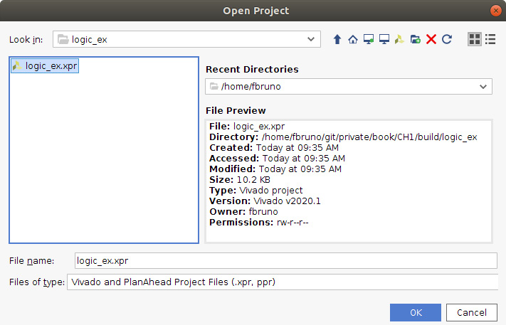
Figure 1.16 – Open Project window
Once open, you'll see the following:
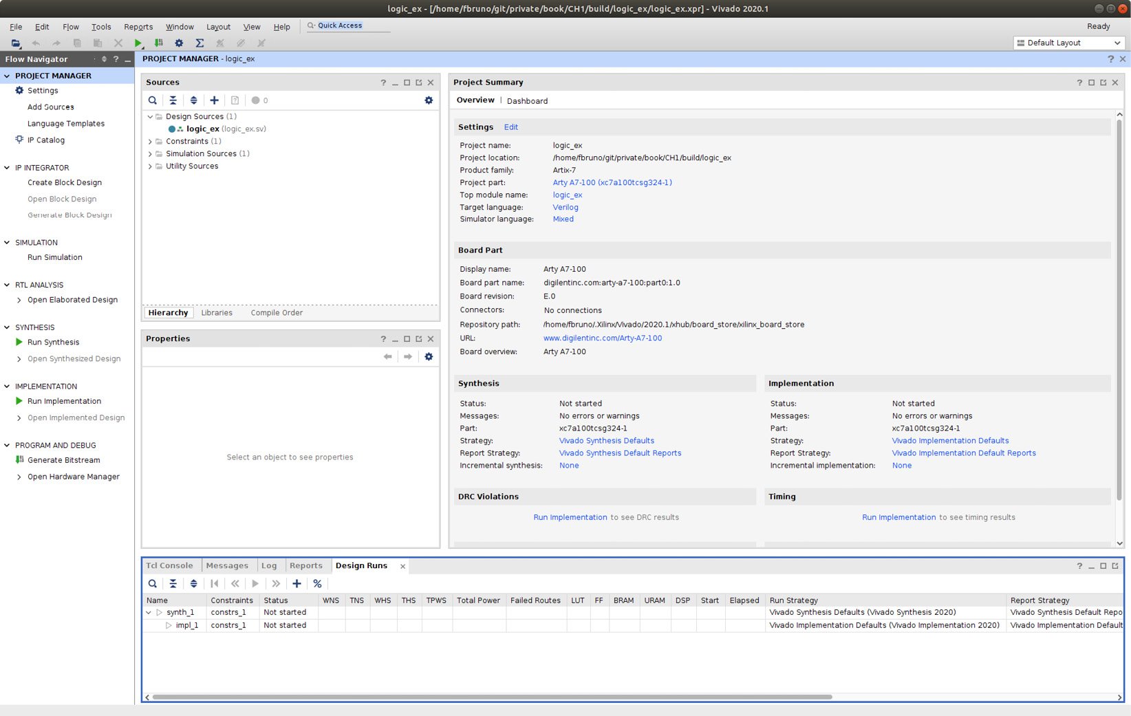
Figure 1.17 – Vivado main screen for the logic_ex project
The Vivado project window gives us easy access to the design flow and all the information relating to the design. On the left-hand side, we see Flow Navigator. This gives us all the steps we will use to test and build our FPGA image. Currently, PROJECT MANAGER is highlighted. This gives us easy access to the sources in the design and the project summary. The project summary should be empty since we have loaded the project for the first time. On future loads of the project, it will display the information from the previous run.
Important note
To give you a jumpstart, all the projects in this book come complete with pre-set-up project files. Please see the appendix for instructions on setting up the first project in both project mode and non-project mode. This will guide you for setting up your own projects in the future.
Let's explore the sources in the design:
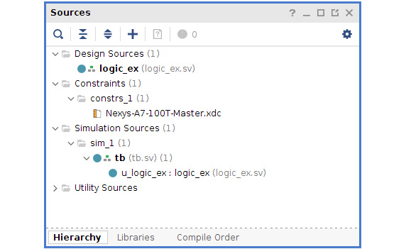
Figure 1.18 – Design sources
Here we can see our design, logic_ex.sv. We also have a set of constraints and we can see the testbench, tb.sv, instantiating logic_ex.sv under simulation sources. You can double-click on any of the files and explore them in the context-sensitive editor built into Vivado. The project is currently set up to reference the files in their current location within the directory structure, so the file can be edited with whatever your favorite editor is.
Looking at Project Summary, we can see the project is currently targeting the Arty A7-100 board.
Running a simulation
First, let's run the Vivado simulator to check the validity of our design.
To do this, click Run Simulation | Run Behavioral Simulation under PROJECT MANAGER. You will see that there are some other options available that are grayed out. These options allow you to run post synthesis or post implementation with or without timing. Behavioral simulation is relatively quick and will accurately represent the function of your design if the code is written properly. I would recommend not running post synthesis or implementation simulation unless you are debugging a board failure and need to accurately test the implemented version of the design as you'll find that the simulations will slow down dramatically.
Running the behavioral simulation will elaborate the design, the first step in the overall flow. The simulation view will take over the Vivado main screen:
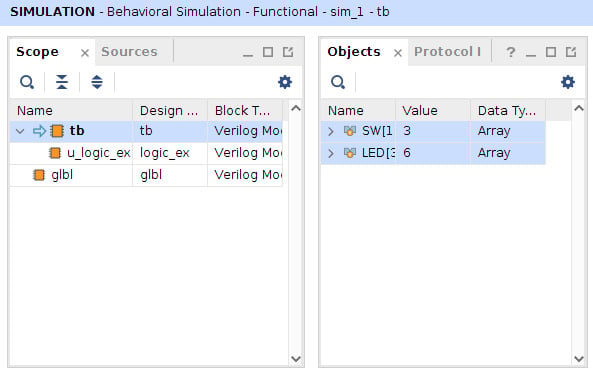
Figure 1.19 – Simulation view
The Scope screen gives us access to the objects within a given module. In this case, within the testbench (tb), we can see two signals, SW[1:0] and LED[3:0]. I've added them to the waves and expanded the view:
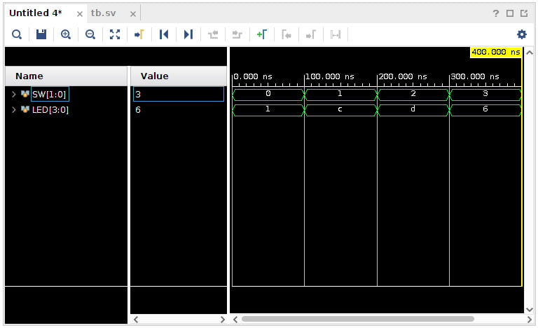
Figure 1.20 – Wave view
The wave view allows us to look at the signals in the design and how they are behaving as the simulation progresses. This will be the most widely used feature of the simulator when debugging problems. We can see the SW signal incrementing due to the for loop in the testbench. Correspondingly, we see the LED values change. The current display is in hex, but it is possible to change it to binary or, by clicking on the > symbol to the right of the signal, to display the individual bits of the signal. Also notice that each change in the signals corresponds to a 100ns time advance. This is due to the #100 we are using to advance time and the timescale setting.
The final window is the most important for a self-checking testbench:
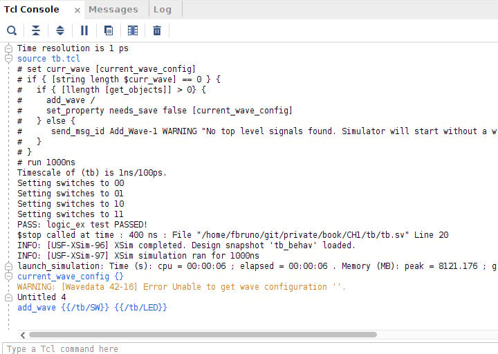
Figure 1.21 – Tcl Console
The Tcl console will display all the outputs from $display, or assertions in the design. In this case, we can see the output from our $printtimescale(tb) function as 1ns/ 100ps. We also see the values that the switches are set to and can see within the waves the same values. Finally, we see PASS: logic_ex test PASSED!, giving us the result of the test. I would encourage you to experiment with the testbench. Change the operators or invert them to verify that the test fails if you do. This exercise will give you confidence that the testbench is functioning correctly.
The goal of verification is not to ensure the design passes; it is to try to make it fail. This is a simple case, so it is not really possible, but make sure that you test unexpected situations to make sure your design is robust.
Tip
It is advisable to adopt a convention in how you indicate tests passing and failing. This test is simple. However, a much more robust test suite for an actual design may have random stimulus and many targeted tests. Adopting a convention such as displaying the words PASS and FAIL allows for easy post-processing of test results.
Implementation
Now that we have confidence that the design works as intended, it is time to build it and test it on the board.
First, let's look at the .xdc file. Click back on Project Manager in Flow Navigator, and then expand the constraints and double-click on the xdc file.
The following lines should be uncommented out for the Arty A7-100T to set the configuration voltages:
set_property CFGBVS VCCO [current_design]
set_property CONFIG_VOLTAGE 3.3 [current_design]
set_property is the tcl command, which will set a given design property used by Vivado. In the preceding command, we are setting CFGBVS and CONFIG_VOLTAGE to the values required by the Artix-7 FPGA.
The following code block sets up the switch and LED locations (placed together for convenience):
set_property -dict { PACKAGE_PIN J15   IOSTANDARD LVCMOS33 } [get_ports { SW[0] }]; #IO_L24N_T3_RS0_15 Sch=sw[0]
set_property -dict { PACKAGE_PIN L16   IOSTANDARD LVCMOS33 } [get_ports { SW[1] }]; #IO_L3N_T0_DQS_EMCCLK_14 Sch=sw[1]
set_property -dict { PACKAGE_PIN H17   IOSTANDARD LVCMOS33 } [get_ports { LED[0] }]; #IO_L18P_T2_A24_15 Sch=led[0]
set_property -dict { PACKAGE_PIN K15   IOSTANDARD LVCMOS33 } [get_ports { LED[1] }]; #IO_L24P_T3_RS1_15 Sch=led[1]
set_property -dict { PACKAGE_PIN J13   IOSTANDARD LVCMOS33 } [get_ports { LED[2] }]; #IO_L17N_T2_A25_15 Sch=led[2]
set_property -dict { PACKAGE_PIN N14   IOSTANDARD LVCMOS33 } [get_ports { LED[3] }]; #IO_L8P_T1_D11_14 Sch=led[3]
The set_property commands create a tcl dictionary (-dict) containing PACKAGE_PIN and IOSTANDARD for each port on the design. We use the get_port TCL command to return a port on the design. # is a comment in the TCL.
The pin locations and I/O standards are defined by the board manufacturer. They have used 3.3 V I/Os and the pins are as specified.
The steps to generate a bitstream are as follows:
- Synthesis: Map
SystemVerilogto an intermediate logic format for optimizing. - Implementation: Place the design, optimize the place results, and route the design.
- Generate bitstream: Generate the physical file to download to the board.
These can be run individually. You might take this route if you need to look at the intermediate results to see how the area or timing is coming out, or if you are designing a custom board and need to do pin planning. In our case, we can click directly on Generate Bitstream and allow it to run all the steps automatically for us. Allow it to use the defaults. When complete, open the implemented results:
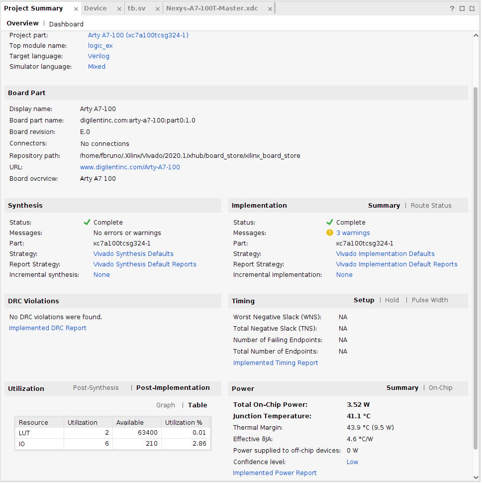
Figure 1.22 – Project Summary
Here we can see the summary of our implementation. We are using 2 LUTs and 6 I/Os (SW + LED). There is no timing since this design is purely combinational, otherwise we'd see more information regarding timing numbers.
If we click the Device tab, we can get a picture of how the device is being used:
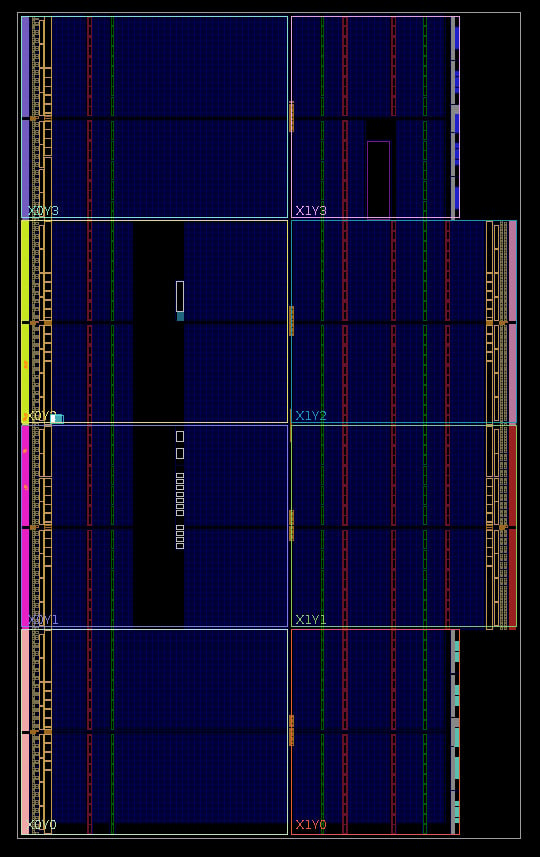
Figure 1.23 – Device view
Here we can see the little white dot midway down the left-hand side. This represents where the LUTs are being placed.
Program the board
You have made it to the end of the chapter and now it's time to see the board in action:
- Make sure it is plugged in and turned on.
- Now, click on Open hardware manager, the last option under Flow Navigator. The hardware manager view will open in the main window.
- Click Open target | Autoconnect.
- Now, select the program device. The bitstream should be selected automatically. The lights will go out on the board for a few seconds and then, if the left two switches are down, you will be greeted with this:

Figure 1.24 – Board bringup
- Flip the switches, and go through 00, 01, 10, 11, where 0 is down, 1 is up. Do the lights match the simulation? Do they match what you think they should be? Do you occasionally see one flicker as the switches are flipped? The last question will be answered in Chapter 3, Counting Button Presses.
Congratulations! You've completed your first project on an FPGA board. You've taken the first step on this journey and reconfigured the hardware in the FPGA to do some simple tasks. As we go through the book, the tasks will become more complex and more interesting and soon you'll be able to build upon this to create your own projects.


