M5Stack Core2 touchscreen UI controls introduction
The M5Stack Core2 is an enhanced version of the original Core unit. As with the original Core unit, the Core2 uses an ESP32-based microcontroller for providing internal hardware components such as the RGB bars, speaker, microphone, gyro, and accelerometers. An internal vibration motor is included with the M5Stack Coe2 unit. The M5Stack Core2 uses a specialized IC to operate a capacitive touchscreen. The touchscreen is overlayed with a Thin Film Transistor (TFT) LCD. Figure 6.1 shows a conceptual diagram of the M5Stack Core2’s touchscreen assembly. As shown in the conceptual diagram, the specialized IC is a touchscreen controller responsible for touch detection and processing of a human finger:
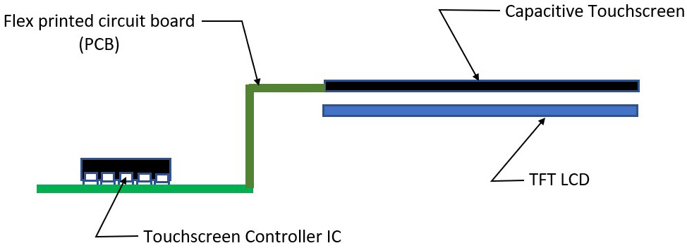
Figure 6.1: M5Stack Core2 touchscreen conceptual diagram
The touchscreen controller IC has a microcontroller that allows touch detection and processing actions. The flexible printed circuit board (PCB) allows touch detection and processing signals to be sent and received by the touchscreen controller IC. Further, the TFT LCD allows the user to interact with Ul’s visual imagery layout. The M5Stack Core2’s UI layout is created using UiFlow Blockly code. The M5Stack Core2 is shown in Figure 6.2:
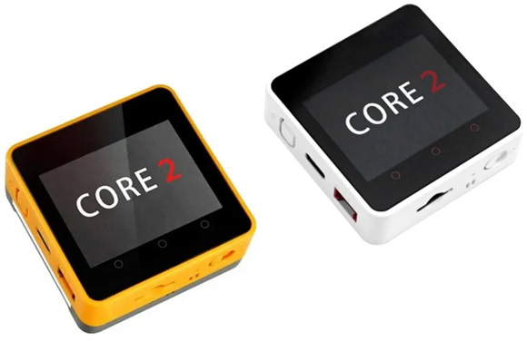
Figure 6.2: M5Stack Core2
The UI touchscreen buttons are located on the bottom portion of the M5Stack Core2 and are identified as three circles. Text can be placed above the three circles for personalizing specific control functions to be initiated by the M5Stack Core2. Figure 6.3 illustrates the location of the M5Stack Core2 touchscreen buttons:
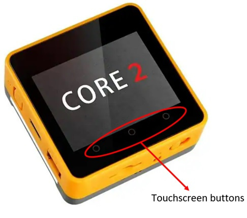
Figure 6.3: Touchscreen buttons
You can program the touchscreen buttons to provide various interactive control functions. Accomplishing this task requires accessing the UI palette within the UiFlow software. You will first need to establish communication with the M5Stack Core2. To do so, connect the M5Stack Core2 to your development machine using the USB-C cable. Insert one end of the USB-C cable into the M5Stack Core2. The other end of the USB-C cable you will insert into your development machine. The UiFlow splash screen will be visible on the M5Stack TFT screen. You will touch the flow button to advance to the choose mode screen. Touch the USB button, then the M5Stack Core2 will reset. After the unit resets, it will be in USB mode. Figure 6.4 shows the steps for setting the M5Stack Core2 into USB mode:

Figure 6.4: Setting M5Stack Core2 into USB mode
Quiz 1
____________ has a microcontroller that allows touch detection and processing actions to occur.
Once you have completed the steps, the M5Stack Core2 will have a visual image and message, as displayed in Figure 6.5:
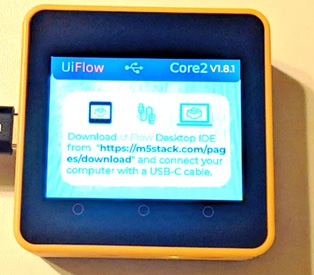
Figure 6.5: M5Stack Core2 in USB mode
Note
Here are the M5Stack Core2 power management operations:
Power on: One click with the power button on the left
Power off: Long press the left power button for 6 seconds
Reset: Click the RST button on the button side
Congratulations on setting up the USB communications mode for the M5Stack Core2! You will now proceed to provide a data connection with the UiFlow software. Open the UiFlow software and select the appropriate common (COM) port and the M5Stack Core2 device. Click the OK button after you have selected your COM port and M5Stack Core2 device. Figure 6.6 shows the selection of the COM port and the M5Stack Core2 device:
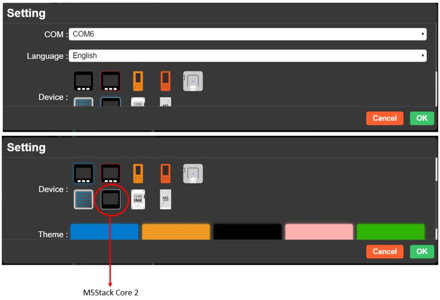
Figure 6.6: COM port and the M5Stack Core2 device selection
Note
You can use Device Manager to determine your COM port. Of the three visible devices under Ports (COM & LPT), select the Silicon Labs COM port!
You can easily create a touch control application with M5Stack Core2 by placing a button on the UI layout. With the button placed, you will select from the UI Blockly code palette the Button option and the touch_Button0_was pressed code block. Figure 6.7 shows the selection of these coding items:
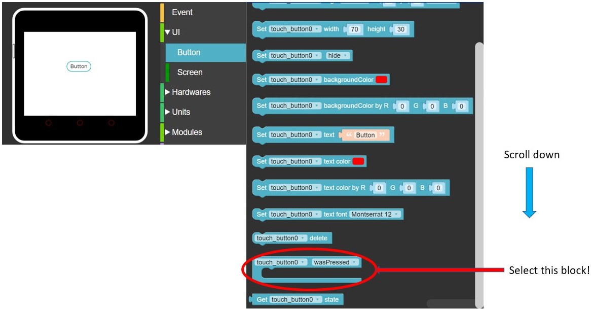
Figure 6.7: UI Button option and code block
Place the touch_Button0_wasPress code block onto the programming screen. You will now proceed to build a basic Hello World application. The Hello World application simply works by pressing the button, displaying the Hello World text, and turning on the red bars. Figure 6.8 shows the Hello World code blocks. Click the RUN button to activate the application. Touch the button to display Hello World!! and turn on the red bar:
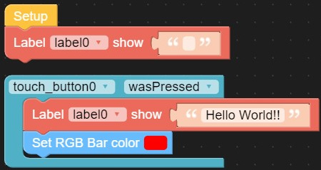
Figure 6.8: Touch-activated Hello World application
Congratulations—you have built your first interactive M5Stack Core2 touch control device! You will now add another button to turn off the red bar and clear the Hello World message from the TFT LCD. The UI for this new control feature is shown in Figure 6.9:
Interactive quiz 1
Using the Blockly code in Figure 6.8, what visual effect will be seen when the Label-show and the Set RGB Bar Color blocks are reversed?
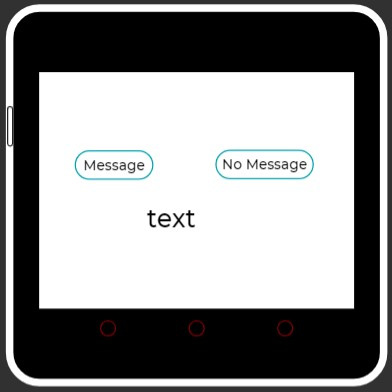
Figure 6.9: Hello World – enhanced UI controls
To see the visual effect of the Hello World message display on the TFT LCD and the red bar turned on, click the Run button on the UiFlow taskbar. Touch the Message button to see the visual effects in action. Clicking the No Message button clears the TFT LCD and turns off the red bar. Figure 6.10 illustrates the visual effects of the enhanced Hello World application:
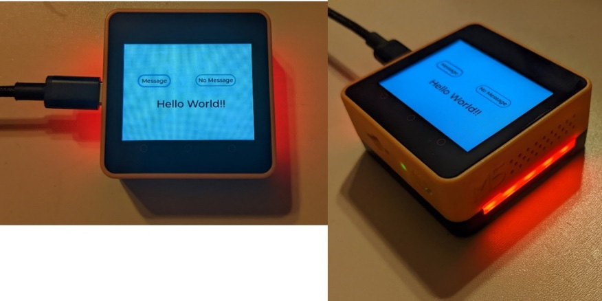
Figure 6.10: The executed Hello World application
You now have the technical skills to proceed to the next project, whereby a touch control inverting switch will be constructed. The M5Stack Core2 will be wired to an Arduino Uno, equivalent to creating an inverting switch. Again, congratulations on completing the touchscreen UI controls introduction!


