Introducing ArchiMate®
The ArchiMate® is a visual modeling language that is published by The Open Group® especially to be able to model and create EA artifacts. It is a complementary extension to TOGAF®, so it provides architects with an extended metamodel, extended taxonomy, and a visual modeling notation.
Important Note
It is highly advisable to get yourself familiar with ArchiMate® if you have not used it or read about it before because all of the information you need for that is already available online. The ArchiMate® 3.1 Specification is easy to navigate, online, and free to all content that is published by The Open Group®, the same publisher of TOGAF®: https://pubs.opengroup.org/architecture/archimate3-doc/.
Architects are free, of course, to use any modeling language they are familiar with to build their artifacts, such as the Unified Modeling Language (UML), System Modeling Language (SysML), Business Process Modeling Notation (BPMN), Data Flow Diagrams (DFDs), and Entity Relationship Diagrams (ERD).
Each of these modeling languages is good for a specific set of artifacts but you will start to struggle when trying to mix elements from different architecture layers within the same view, which is what EA is all about.
Let's see why ArchiMate® is preferable over the other modeling languages for developing EA artifacts.
ArchiMate®'s role in EA artifacts
If you are modeling for the purpose of software development only, then UML and SysML would be ideal, and people have used them for years. However, if you are developing EA artifacts, you may need to model strategy and motivation elements along with the software components, which can be a bit difficult to do without some workarounds. The same thing is true when you chose BPMN for modeling business processes. BPMN is a familiar notation for most business and IT stakeholders, which makes it the default choice for modeling business processes. However, you cannot use it to model software or hardware components, or to model data structures and object relationships.
This is where ArchiMate® comes to the scene and is gradually becoming the choice for many enterprise architects. With ArchiMate®, you can have elements from the Technology Architecture layer (a node, for example) serving an element from the Application Architecture layer (an application component, for example), which serves a component from the Business Architecture layer (a business service, for example), which realizes an element from the Motivation Layer (a goal, for example), all in one diagram. There is no other modeling language than ArchiMate® that can handle this mixture in one place:
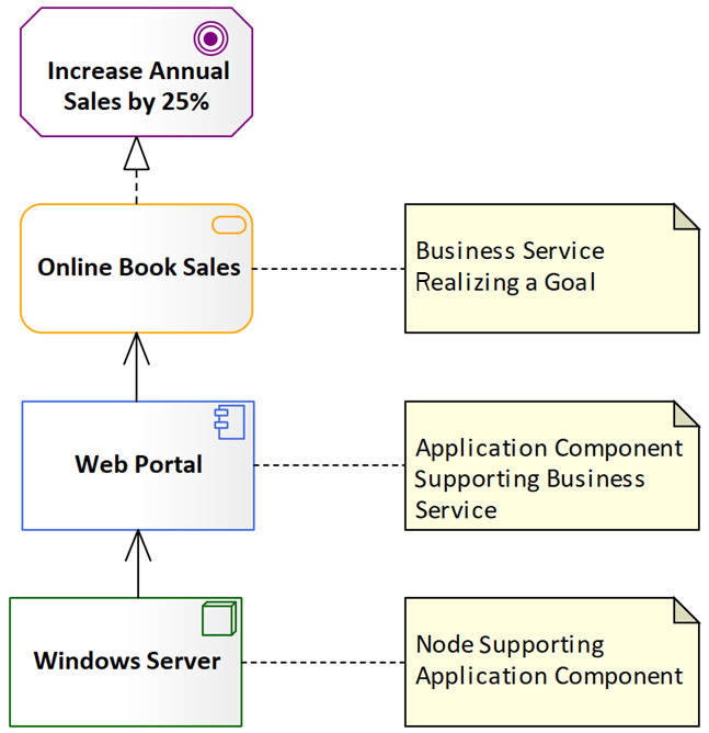
Figure 1.2 – An ArchiMate® example showing elements from different layers
To be fair, with UML, you can extend the basic UML elements such as the classes and the components using stereotypes to get any EA element you need. In the preceding example, you could have used a class with the <<goal>> stereotype, a class with a <<business service>> stereotype, a component with the <<application component>> stereotype, and a component with the <<technology component>> stereotype, respectively.
You must, however, limit the list of stereotypes that you will use to the elements that you have defined in your metamodel to avoid having too many stereotypes and losing the meaning of elements' identification and classification. Additionally, you need to make sure that you consistently follow the same spelling for stereotypes. You are free to use <<application component>>, <<ApplicationComponent>>, <<Application Component>>, or any other way you prefer, but you must stick to the same within the entire EA repository or else you will end up having multiple different classes representing the same type of elements. This is where metamodels become very handy because you can always refer to them to check which format you used. The following diagram shows how you can model the same information in the previous ArchiMate® diagram using UML and stereotypes:
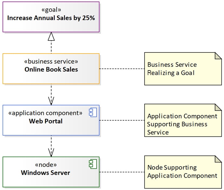
Figure 1.3 – An example of EA artifacts modeled using UML
Notice that UML does not have the support relationship, so we must replace it with the dependency relationship and change its direction. The preceding diagram can now be read as the goal is realized by a business service, which depends on an application component, which depends on a node (or a technology component).
Tip
Always keep UML as a possible option in your mind for modeling EA artifacts as many organizations prefer to use it instead of introducing a new modeling language such as ArchiMate®. A new modeling language will require additional change management efforts that will be translated to additional investment in time and money.
The good news is that everything you will learn from this book can be done with UML. I have built more EA repositories using UML than with ArchiMate®, so it is a quite common and acceptable approach.
Understanding ArchiMate® modeling specification
The ArchiMate® specification has been defined in multiple versions by The Open Group® but the latest is version 3.1 and it is the one that we will be following. We will not repeat the information that is available online, but we will use some of the elements in more detail and we will map them to TOGAF®'s artifacts. In this section, we will cover the following:
- ArchiMate® 3.1 element hierarchy
- Elements color theme
- ArchiMate® modeling notation
Let's explore in more detail each one of them.
Exploring ArchiMate® 3.1 element hierarchy
ArchiMate® categorizes elements into two main categories regardless of the layer: structural and behavioral. Structural elements are the elements describing objects and entities; therefore, they are also known as nouns. Structural elements can be subdivided into active and passive. Active structural elements are the ones that perform the actions while passive structural elements are what actions are performed on. This makes application components, for example, active structural elements while data objects are passive structural.
Active structural elements can be further subdivided into internal and external elements based on how exposed they are to the surrounding environment. An application component can be accessed only through an application interface, for example. Whether the interface is a User Interface (UI) or an Application Programming Interface (API), actors must use interfaces to communicate with components.
Behavioral elements describe the actions that structural elements can perform, so you can think of them as the verbs that nouns can perform on other nouns. Behavioral elements can also be subdivided into internal and external elements. Internal behaviors, such as processes, describe how the structural elements get the job done. External behaviors, such as services, describe to the external environment what the structural elements provide to them.
Confused? Do not worry because this part was meant to help you in reading the official ArchiMate® metamodels, which we will replace with a much easier-to-read metamodel, so please be patient. Just explore the following diagram, which summarizes the hierarchy of ArchiMate® 3.1 elements, but you do not have to remember any of it for now:
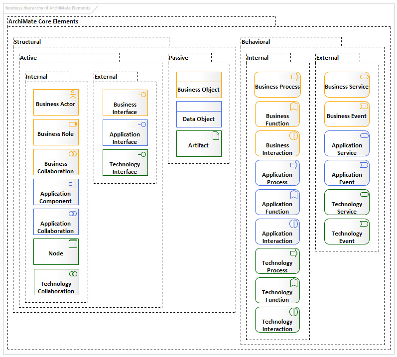
Figure 1.4 – The hierarchy of ArchiMate® 3.1 core elements
The layers and the elements in the preceding diagram are known as the core elements. There are additional layers and elements, but our focus will be on the core elements, which we will use most of the time. We will explore other non-core elements as we need them.
Exploring elements color theme
There is no strict color theme that ArchiMate® forces architects to follow, so you are free to follow any coloring theme or simply make everything in black and white as long you consistently follow the same practice in all your diagrams. If you chose blue, for example, for application layer elements, then it's a good idea to stick to the exact same shade of blue in all the diagrams throughout the entire repository. Using the same color for elements that belong to different architecture layers can be confusing. You can also use black and white for everything to avoid complicating the rules for you and/or your team.
Also keep in mind that some regulations may require using specific color codes and some regulations restrict the usage of colors to differentiate between objects, so make sure that you comply with the regulations of the region you live in.
As a result, it is better to use the named ready-made colors instead of creating custom colors that require remembering their RGB codes every time you use them. Your metamodels can also tell the colors of the elements that need to be followed across the repository.
Note
If you are reading a printed copy of this book, then some diagrams will be in grayscale. For full-color versions of these diagrams, please refer to the graphic bundle available here: https://static.packt-cdn.com/downloads/9781801076166_ColorImages.pdf.
ArchiMate®'s online documentation consistently uses yellow for business, blue for application, and green for technology layer elements. The entire shapes are filled with the proper colors surrounded by black borders:

Figure 1.5 – The color theme of ArchiMate®'s online content
We will follow a similar coloring theme in this book, but we will fill the elements with white and apply the colors to the borders. We will also use orange for business elements instead of yellow for better visibility:

Figure 1.6 – The color theme of this book
The color names of the preceding are defined in Sparx as follows:
- Orange (RBG 255, 165, 0); will be used for all Business Architecture elements
- Royal Blue (RBG 65, 105, 225); will be used for all Application Architecture elements
- Dark Green (RGB 0, 100, 0); will be used for all Technology Architecture elements
As mentioned earlier, it is up to you to decide what colors to use as long as you and other EA team members remain consistent with your choice.
Introducing ArchiMate®'s modeling notations
ArchiMate® provides two notations to represent each type of element. As you can see in Figure 1.7, one uses rectangular shapes with small icons in the top-right corner of the rectangle (Rectangular Notation), and the other uses large versions of the icons without the rectangular borders (Borderless Notation). ArchiMate® uses shapes rather than textual stereotypes to visually differentiate elements, which can be confusing at the beginning until you get used to all the different shapes.
Have a look at the following diagram and notice the differences between the two notation styles. The top row uses the rectangular notation to model an application interface, an application component, and an application function, respectively. The small icons in the top-right corner of each rectangle represent the type of element. The bottom row uses the borderless notation to model the same three elements we mentioned previously in the same order.
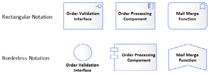
Figure 1.7 – ArchiMate®'s two notations
There is no difference at all between the two notations; it is just a matter of preference. You can switch between the two styles in Sparx by simply right-clicking on the shape and checking or unchecking Advanced > Use Rectangle Notation from the context menu. The captions will always be inside the rectangular shapes, while they may get placed outside the borderless shapes for some elements. If you are modeling a composition relationship, you can do this by placing one element inside the other, and the container element will be the whole or the parent and the contained element will be the part or the child. In the composition scenario, I recommend using the rectangular notation for the container to have more space inside.
In general, avoid using the two notation styles in the same diagram for the same element type as this will confuse your audience. For example, do not use the rectangular notation to represent some application interfaces and use the borderless notation to represent some other application interfaces on the same diagram because this will indicate that there is a difference between the two. We will explore the two different notations as we go, and we will use one style in some diagrams and use the other style in some other diagrams but will never mix the two in a single diagram.
Metamodels
ArchiMate® has extended TOGAF®'s metamodel by adding more elements and more relationships. But unlike TOGAF®'s metamodel, where all the elements and relationships are displayed in a single diagram, ArchiMate®'s metamodel is divided down into smaller but closely related metamodels, so there is a metamodel for the motivation layer, a metamodel for the business architecture layer, a metamodel for the application architecture layer, and so on. The reason – I believe – is to avoid having a big, busy diagram that is difficult to understand.
Important Note
Please refer to Figure 30-5 from TOGAF® 9.2 for the core content metamodel, and Figure 30-7 for the full content metamodel (https://pubs.opengroup.org/architecture/togaf9-doc/arch/chap30.html). You need to make yourself familiar with how TOGAF® and ArchiMate®'s metamodels are defined and how can you interpret them as this is an essential step for applying the standards to ensure that the architecture content is in full alignment with the framework.
In this section, we will talk about the following:
- ArchiMate® 3.1 metamodels
- ArchiMate® taxonomy
The following subsections provide more details for each.
ArchiMate® 3.1 metamodels
ArchiMate® metamodels are written in a very abstracted way in order to provide wider coverage of enterprise elements in a smaller space. They contain elements such as the Application Internal Behavior Element to represent all descendant elements, rather than putting each of them on the diagram and complicating it with intersecting relationships. Check this ArchiMate® metamodel online to be able to follow my explanation: https://pubs.opengroup.org/architecture/archimate3-doc/chap09.html#_Toc10045390.
As you can see, the metamodel tells you a lot of things that can help you when you are modeling application layer components, and they have tried to make it as compact as possible. If you want to model an application component, for example, the metamodel will tell you what other elements can connect to or be in a relationship with your component.
As you can see, there is no application component in the diagram but the more generic class, the Application Internal Active Structure Element class, which can be confusing for those who are new to ArchiMate®. It tells us that application components can be assigned to an application internal behavior element, which can be translated to the application component that can execute the application process.
It will take you some time to be able to quickly interpret the ArchiMate® metamodels, but the good news is that we will be presenting metamodels differently and easily throughout this book.
The ArchiMate® taxonomy
Since ArchiMate® and TOGAF® are published by the same organization, you're better off thinking of ArchiMate®'s taxonomy as an extension of TOGAF®'s taxonomy rather than two different ones. The definitions of the two are very similar and in many cases, they are exactly the same. But because TOGAF® is more generic and ArchiMate® is more detailed, you may find that a single definition in TOGAF® has multiple specific definitions based on the architecture layer they belong to. For example, TOGAF® has a single definition for process, while ArchiMate® has three layer-specific definitions for it: business process, application process, and technology process.
We will include both definitions when introducing new elements and will try to add more elaborate descriptions supported with examples to clarify them. Some definitions are written in a difficult-to-understand language, so we will try to simplify that. Definitions will be quoted as is from the sources and will always be in italics to be easily differentiated from the rest of the text. The following is an example of the definition of a business process:
A business process represents a sequence of business behaviors that achieves a specific result such as a defined set of products or business services (ArchiMate® 3.1: https://pubs.opengroup.org/architecture/archimate3-doc/chap08.html#_Toc10045374).
Any additional elaboration and supportive examples will usually come in the paragraph following the definition, like this paragraph.
The next section will introduce Sparx Systems Enterprise Architect as our tool of choice for modeling EA artifacts.
Introducing our focused metamodels
Reading about and understanding the ArchiMate® metamodels can make the difference between a true architectural artifact and any other diagram. But as you saw, it is not a straightforward step to get the information you want. I used to use paper and pen to decipher the metamodels into something that I can use in my models. When it comes to connecting to elements from other layers, you must refer to the metamodels that define the cross-layer relationships to get the bigger picture.
Since this book is all about making things more practical, we are providing you with metamodels that are focused on one element at a time. The following diagram represents the application component-focused metamodel and I bet it looks way easier to read and understand than the standard ArchiMate® metamodel:
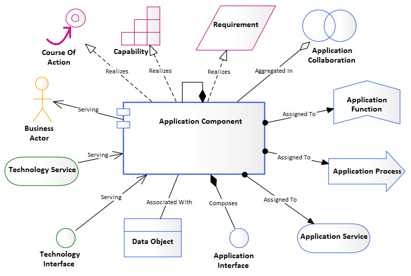
Figure 1.8 – Application component-focused metamodel
You can immediately tell that an application component can be assigned to an application function, application process, and application service. It can compose application interfaces and can compose other application components as well. We will cover in more detail all the components that are included in the focused metamodel.
Following a metamodel is essential in unifying the EA artifacts that are developed by different architects. They are the blueprints for developing models, and without them, each diagram will look different and be inconsistent. You do not have to include all the elements that are shown in the focused metamodels in every model you develop. It is a reference that shows every relationship possibility, so you take only the ones you need.
Additionally, do not forget that we are following an agile way of implementing EA, so we do not have to develop all the focused metamodels before we start modeling as this is a waterfall approach. As we start following the example scenarios in Section 2 and Section 3 of this book, we will build only the metamodels that we will need. Even if we do not cover every element in the ArchiMate® specification, you should be able to build the metamodels for the remaining ones and populate your own EA repository in the same way that we will be practicing.


