Assembler – transforming assembly code into machine code
At this moment, you may notice that something is not quite right. The processor chips we use every day are not capable of executing text-based assembly code but are instead parsed into the machine code of the corresponding instruction set to perform the corresponding memory operations. Thus, during the compiling process, the previously mentioned assembly code is converted by the assembler into the machine code that can be understood by the chip.
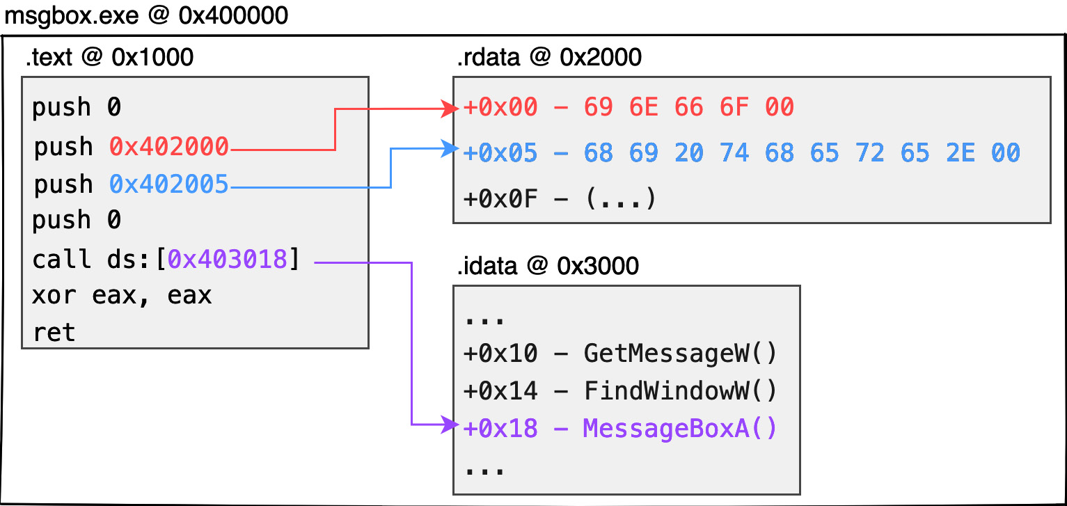
Figure 1.2 shows the dynamic memory distribution of the 32-bit PE:

Figure 1.2 – 32-bit PE memory layout
Since the chip cannot directly parse strings such as hi there or info, data (such as global variables, static strings, global arrays, etc.) is first stored in a separate structure called a section. Each section is created with an offset address where it is expected to be placed. If the code later needs to extract resources identified during these compilation periods, the corresponding data can be obtained from the corresponding offset addresses. Here is an example:
- The aforementioned
infostring can be expressed as\x69\x6E\x66\x6F\x00in ASCII code (5 bytes in total withnullat the end of the string). The binary data of this string can be stored at the beginning of the.rdatasection. Similarly, thehi therestring can be stored closely after the previous string at the address of the.rdatasection at offset +5. - In fact, the aforementioned
call MessageBoxAAPI is not understood by the chip. Therefore, the compiler will generate anImport Address Tablestruct, which is the.idatasection, to hold the address of the system function that the current program wants to call. When needed by the program, the corresponding function address can be extracted from this table, enabling the thread to jump to the function address and continue executing the system function. - Generally speaking, it is the compiler’s practice to store the code content in the
.textsection. - Each individual running process does not have just one PE module. Either
*.EXEor*.DLLmounted in the process memory is packaged in PE format. - In practice, each module loaded into the memory must be assigned an image base address to hold all contents of the module. In the case of a 32-bit
*.EXE, the image base address would normally be0x400000. - The absolute address of each piece of data in the dynamic memory will be the image base address of this module + the section offset + the offset of the data on the section. Take the
0x400000image base address as an example. If we want to get theinfostring, the expected content will be placed at0x402000(0x400000 + 0x2000 + 0x00). Similarly,hi therewould be at0x402005, and theMessageBoxApointer would be stored at0x403018.
Important note
There is no guarantee that the compiler will generate .text, .rdata, and .idata sections in practice, or that their respective uses will be for these functions. Most compilers follow the previously mentioned principles to allocate memory. Visual Studio compilers, for example, do not produce executable programs with .idata sections to hold function pointer tables, but rather, in readable and writable .rdata sections.
What is here is only a rough understanding of the properties of block and absolute addressing in the dynamic memory; it is not necessary to be obsessed with understanding the content, attributes, and how to fill them correctly in practice. The following chapters will explain the meaning of each structure in detail and how to design it by yourself.
In this section, we learned about the transformation to machine code operations during program execution, as well as the various sections and offsets of data stored in memory that can be accessed later in the compiling process.


